

Understanding Sheet Metal Tolerances in Real Fabrication
In sheet metal enclosure development, it is common for designs to pass drawing review smoothly yet struggle the moment assembly begins. Every dimension may be within tolerance, hole locations may match the drawing, and bend angles may be specified correctly. But, during assembly, panels don't line up, fasteners need extra force, and gaps look uneven.
This isn’t unusual, and it’s rarely a sign of poor fabrication. The problem usually comes from how sheet metal tolerances behave once cutting, bending, and forming processes interact. Enclosures are made up of parts that have to work together and not just meet specs on their own. Tolerances that look acceptable on paper often behave very differently once parts are assembled.
Understanding this behavior is critical for anyone designing sheet metal parts or enclosures intended to assemble cleanly and scale reliably.
Why Sheet Metal Tolerances Behave Differently Than Expected
Solid blocks machining and sheet metal fabrication are very different. Sheet metal fabrication uses cutting and forming to reshape material, whereas machining removes material to achieve shape. Each step introduces its own variability, even under controlled conditions.
Tolerance behavior in sheet metal is influenced by material thickness variation, cutting process accuracy, forming method, tooling geometry, grain direction, and elastic recovery during bending. Throughout the fabrication process, these variables are constantly interacting. As a result, tolerances cannot be treated as discrete numerical limits. They must be understood as ranges shaped by material behavior and process physics.
The Role of Cutting Procedures in Dimensional Variation
The most popular methods for cutting sheet metal parts are punching and laser cutting. Both are precise, but neither is perfectly static.
Laser cutting accuracy depends on kerf width, thermal input, material reflectivity, and sheet flatness. Thin materials can experience slight heat-related distortion, while thicker sheets may show small kerf variations across longer cuts. For individual features, these effects are usually negligible, but when several holes or edges need to line up across large panels, they become significant.
Punching introduces mechanical forces into the sheet. Tool clearance, punch wear, and material hardness affect hole size and positional repeatability. Even when nominal dimensions stay constant, tooling conditions can gradually change the results.
In enclosure design, these variations matter most not at a single hole or edge, but across relative positioning. As compared to single dimensions, hole-to-hole accuracy and edge-to-feature relationships are much more sensitive to tolerance accumulation.
Understanding Springback and Bend Variation
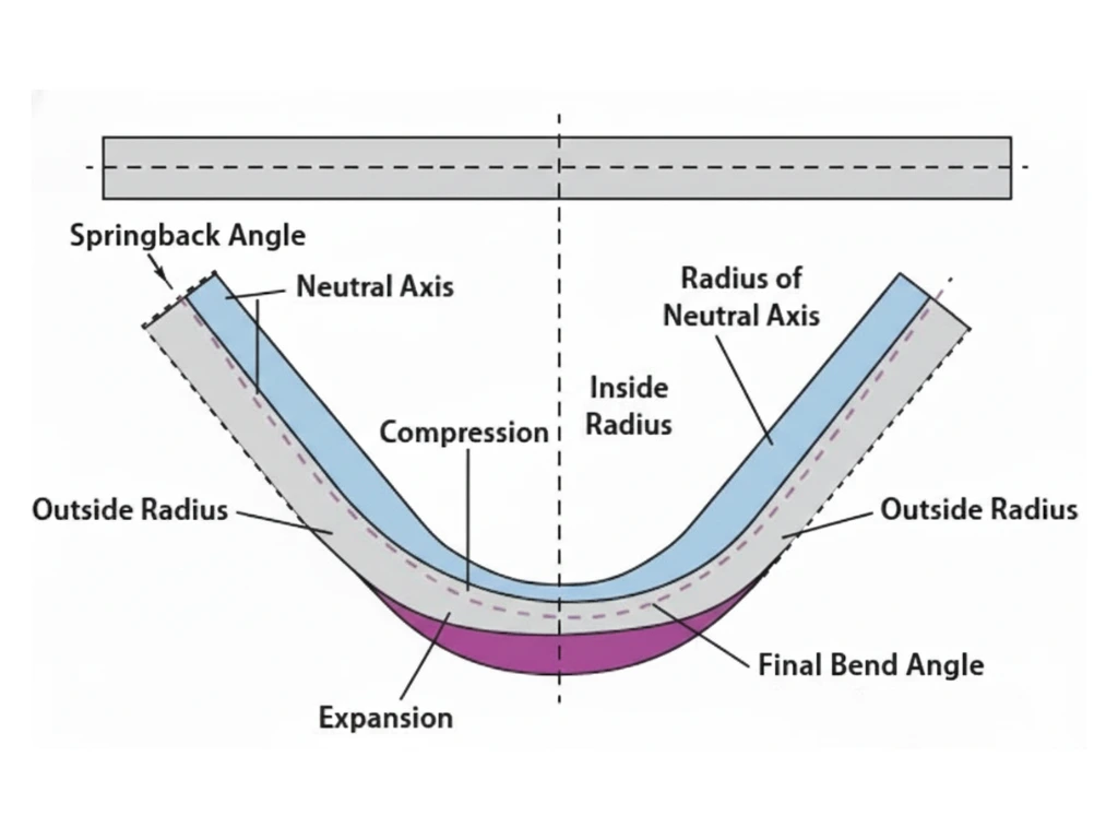
In sheet metal fabrication, bending is the most significant operation and the most common source of unexpected variation. During bending, the material undergoes plastic deformation. Depending on the bend radius and thickness of the material, the neutral axis moves, inner fibers compress, and outer fibers stretch.
Bend accuracy is affected by several interacting factors. The amount of force needed to form the bend depends on the material grade and yield strength. Inconsistent behavior between identical parts can be caused by grain direction. Tooling geometry and press brake calibration affect bend repeatability. Most importantly, elastic spring back causes the material to partially return toward its original shape after forming.
Springback varies with material type, thickness, bend radius, and forming method. Designs that assume a perfectly achieved bend angle without accounting for springback often assemble poorly, even when fabrication follows the drawing precisely.
Flat Pattern Design and Its Impact on Assembly
Flat pattern accuracy plays a critical role in enclosure fit. Bend allowance and bend deduction calculations determine how much material is consumed during forming. Small errors in these calculations propagate across multi-bend parts, leading to noticeable dimensional drift in the final enclosure.
Flat patterns must be calculated based on actual material thickness, bend radius, tooling method, and K-factor. Using generic or assumed values without validating them against real fabrication conditions often results in enclosures that appear dimensionally correct on drawings but fail to align during assembly.
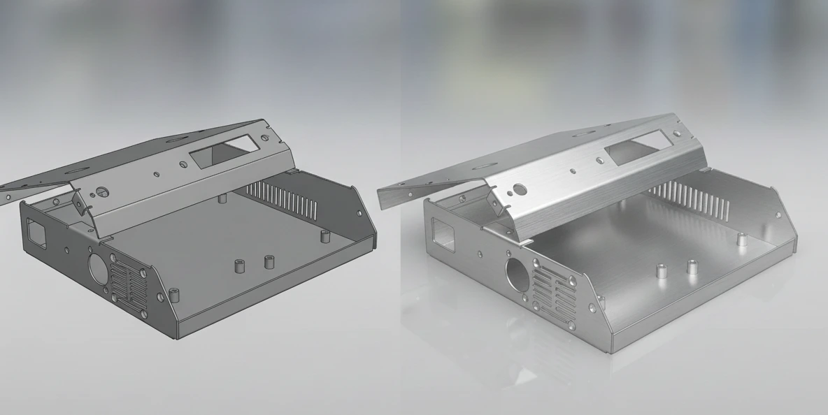
This is especially common in U-shaped chassis, multi-flange panels, and enclosures with stacked bends, where each bend compounds previous variation.
How Tolerance Stack-Up Causes Assembly Failure
Tolerance stack-up occurs when acceptable variations from multiple features accumulate beyond functional limits. In sheet metal enclosures, stack-up typically includes cut edge variation, hole positional tolerance, bend angle deviation, bend location shift, and flatness variation.
Individually, each variation falls within specification. Collectively, they cause misalignment. Fasteners no longer line up easily, panels twist when tightened, and stress builds into the assembly.
This is why assemblies fail despite technically correct parts. The issue is not a single tolerance but how multiple tolerances interact across the enclosure.
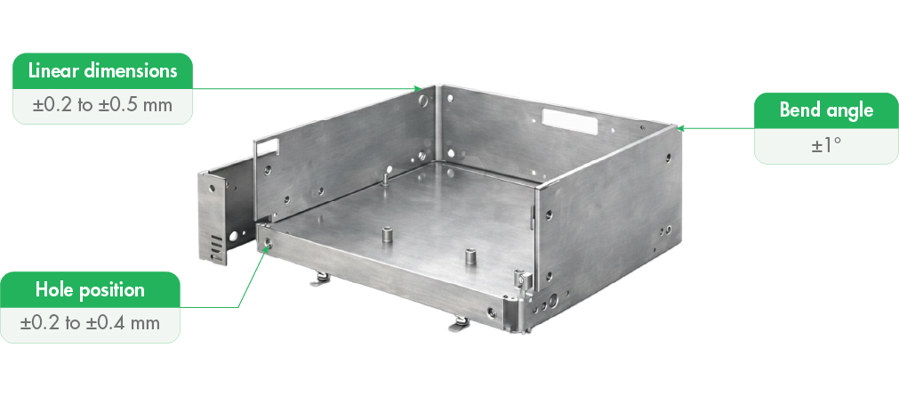
Industry-Common Tolerances for Sheet Metal Fabrication
While exact tolerances depend on material and process, industry guidelines provide realistic expectations. Linear dimensions up to 100 mm typically fall within ±0.2 to ±0.3 mm, while larger dimensions often range between ±0.3 and ±0.5 mm. Hole diameters usually vary within ±0.1 to ±0.2 mm, while hole position tolerance may extend to ±0.2 to ±0.4 mm. Bend angles are commonly controlled within ±1°, and bend location variation typically ranges from ±0.3 to ±0.5 mm.
These ranges are not guaranteed. They are practical design references that help engineers anticipate how parts will behave during fabrication and assembly.
To translate fabrication behavior into design expectations, engineers often rely on practical tolerance ranges rather than theoretical limits. The values below reflect commonly achievable ranges in sheet metal fabrication and help set realistic assembly expectations.
Feature | Typical Tolerance |
Linear dimensions up to 100 mm | ±0.2 to ±0.3 mm |
Linear dimensions above 100 mm | ±0.3 to ±0.5 mm |
Hole diameter | ±0.1 to ±0.2 mm |
Hole position | ±0.2 to ±0.4 mm |
Bend angle | ±1° |
Bend location | ±0.3 to ±0.5 mm |
Flatness | Function of part size and bends |
Why Enclosures Amplify Tolerance Effects
Enclosures amplify tolerance effects because they combine multiple parts into a functional system. Panels must align, fasteners must engage smoothly, connectors must match PCB locations, and clearances must remain consistent. Even small variations become visible and problematic when multiple interfaces depend on alignment.
A slight bend deviation in one panel can offset connector access. A flatness variation can twist the enclosure when fasteners are tightened. These issues are rarely obvious in 2D drawings but become clear during assembly.
This is why enclosure tolerance planning must focus on assembly behavior, not just dimensional compliance.
How Tolerance-Aware Design Improves Assembly
Successful enclosure designs do not attempt to eliminate tolerances. They manage them. This is achieved by breaking tolerance chains, prioritizing functional dimensions, and allowing controlled freedom where variation is unavoidable.
Common strategies include using slots instead of tight holes, allowing floating PCB mounts, avoiding long cumulative bend sequences, and adding clearance where function permits. These design decisions significantly improve assembly yield without increasing fabrication complexity.
Role of CNC Machining in Critical Features
While sheet metal defines enclosure structure, CNC machining supports precision where it matters most. Machined features are commonly used for connector interfaces, threaded inserts, alignment features, and critical mounting surfaces.
By combining sheet metal fabrication with CNC precision machining, designs achieve both flexibility and accuracy without over-constraining the entire enclosure.
Mech Power supports this hybrid approach through integrated sheet metal fabrication and CNC machining services.
Instant Quote for Sheet Metal Cutting and Bending
Design decisions around tolerances often benefit from fast pricing feedback. Mech Power’s Instant Quote allows engineers to upload designs and receive immediate pricing for sheet metal cutting and bending.
This enables faster iteration, better comparison of design options, and earlier tolerance-aware decisions. Instead of waiting for manual quotes, teams can evaluate how design changes impact cost and manufacturability in real time.
Why Tolerance-Aware Design Improves Cost and Reliability
Designing with tolerance behavior in mind does not increase cost. It reduces rework, minimizes manual fitting, improves assembly speed, and enhances long-term reliability. Parts that assemble easily scale better and perform more consistently in real-world use.
How Mech Power Addresses Tolerance Challenges
At Mech Power, sheet metal tolerances are addressed across enclosure design, fabrication, prototype validation, and production planning. The focus remains on manufacturability, assembly flow, and repeatability rather than drawing compliance alone.
This approach ensures enclosures work as intended beyond the CAD stage.
Conclusion
If your enclosure fits on paper but fails during assembly, the cause is rarely fabrication quality. It is usually tolerance behavior shaped by material and process realities.
Sheet metal tolerances are not problems to eliminate. They are conditions to design around. When enclosure designs respect how sheet metal behaves during cutting and bending, assemblies become smoother, faster, and more reliable.
That is the difference between a drawing that measures right and an enclosure that works right.
From enclosure design to fabrication-ready parts
Get started with your part or enclosure, upload your design & Get an Instant Quote.
FAQS
Frequently Asked Questions
Sheet metal tolerances define the allowable dimensional variation that occurs during cutting and bending processes.
Because small allowable variations from multiple parts accumulate and cause tolerance stack-up during assembly.
Bending introduces material deformation and springback, which can shift angles and feature locations.
Tolerance stack-up occurs when multiple dimensional variations combine and exceed functional limits in an assembly.
Enclosures combine multiple parts and interfaces, making small variations more noticeable during assembly.