

In hardware manufacturing, performance variability is rarely accidental. It is usually traceable to how clearly product expectations were defined before production began.
A Product Requirement Document (PRD) is the structured technical framework that translates design intent into measurable engineering parameters. It ensures that dimensional accuracy, environmental performance, and assembly stability are not left to interpretation during manufacturing.
Without structured requirement definition, production teams compensate for ambiguity during fabrication and assembly. That compensation often appears as tolerance conflicts, misalignment, coating interference, or repeated prototype cycles.
What a Product Requirement Document Represents in Manufacturing
In a manufacturing context, a PRD defines performance boundaries, dimensional limits, and environmental expectations in measurable terms.
Unlike conceptual documentation, a manufacturing PRD defines criteria that can be validated during inspection.
A manufacturing-focused PRD answers key engineering questions such as:
What must the product withstand?
What dimensional variation is acceptable?
What environmental conditions apply?
What compliance standards must be met?
The Intersection of Requirements and DFM
A well-structured PRD does more than list constraints; it establishes the baseline for Design for Manufacturing (DFM). While a PRD defines what the product must be, DFM defines how to achieve it with maximum yield and minimum cost.
When manufacturing teams receive a PRD, they look for "hidden risks" that could compromise quality:
Feature Sensitivity: Are the tightest tolerances assigned to surfaces that genuinely interact, or are they applied to non-critical aesthetics?
Geometric Feasibility: Can the specified corners, wall thicknesses, or hole patterns be formed or machined within the material’s standard elastic limits?
Material Selection: Does the chosen material align with the intended process (e.g., sheet metal vs. CNC), or will the inherent material properties necessitate expensive post-processing?
Dimensional Requirements: Allocation vs Assumption
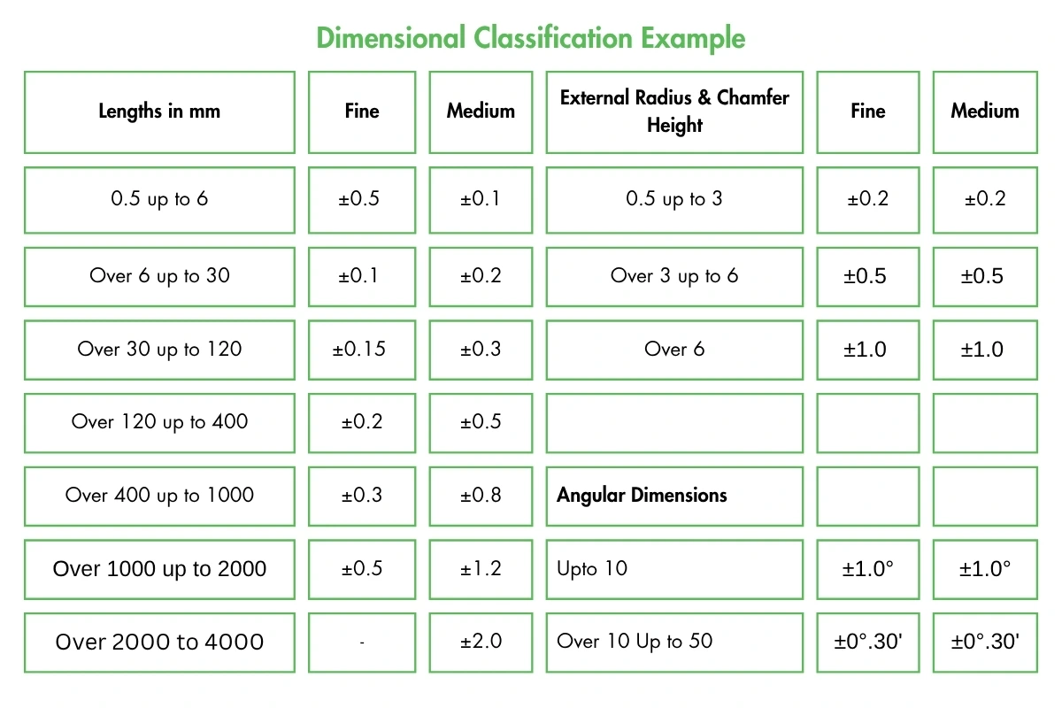
A common mistake in hardware development is treating all dimensions with equal importance. In reality, different features require different levels of precision depending on their function in the assembly.
A structured PRD helps engineers classify dimensions based on their role in the product.
A structured PRD distinguishes:
- Critical Dimensions - functional interfaces or alignment features
- Controlled Dimensions – secondary interfaces
- Reference Dimensions – non-functional measurements
Over-constraining tolerances increases production cost. For example, tightening CNC tolerance from ±0.2 mm to ±0.05 mm may increase machining time by 15–30% depending on geometry.
Surface Finish and Coating Impact
Surface finishing processes such as anodizing or powder coating introduce additional thickness that affects dimensional behavior. If these thickness values are not defined in the PRD, clearance planning may become inaccurate.
For example, powder coating adds material to both sides of a surface. This additional thickness can influence mating components or assembly interfaces.
Powder Coating Example
Powder coating thickness: 80 µm per side
Two mating surfaces = 160 µm total dimensional reduction
If nominal clearance = 0.2 mm
Effective clearance after coating =
0.2 mm − 0.16 mm = 0.04 mm
Neglecting coating thickness in the PRD often results in mechanical interference, stripped threads, or 'forced' assemblies that introduce latent stress into the chassis.
Example of Measurable PRD Parameters
Requirement Type | Defined Parameter | Verification Method |
Functional Load | 250 N static load | Load test validation |
Dimensional Tolerance | ±0.15 mm critical interface | CMM inspection |
Surface Finish | Ra ≤ 1.6 µm | Surface roughness test |
Coating Thickness | 80 µm ± 10 µm | Thickness gauge |
Environmental Range | -20°C to +60°C | Environmental chamber test |
Why Requirement Clarity Matters Before Production
Manufacturing variability does not occur only at the individual part level. It accumulates across multiple components during assembly. When multiple components interact, even minor dimensional differences can grow..
For instance, panels, fasteners, brackets, and mounting interfaces are frequently used in enclosure assemblies. If tolerance limits are not allocated properly across these parts, small variations can combine into noticeable alignment issues during assembly.
Quantified Stack-Up Example
If five mating components each carry ±0.2 mm tolerance:
The Worst-case stack-up is 0.2 × 5 = ±1.0 mm
In enclosure assemblies, a 1 mm deviation may:
- Affect gasket compression
- Misalign mounting holes
- Prevent flush panel alignment
Common Documentation Gaps
Even experienced engineering teams encounter recurring issues related to requirement clarity. These gaps typically appear when specifications are described qualitatively instead of quantitatively.
Undefined vs Structured Requirements
Undefined Requirement | Structured PRD |
“Standard material” | Aluminum 5052-H32 |
“Tight tolerance” | ±0.1 mm critical interface |
“Powder coated” | 70–90 µm thickness |
“Outdoor use” | IP54, UV-resistant coating |
Ambiguity increases interpretation. Structure reduces variability.
The Cost of Requirement Ambiguity
When requirements are not clearly defined, engineering teams often discover issues during prototype validation or early production runs.
Common outcomes include:
- Additional prototype cycles
- Quote revisions due to design adjustments
- Assembly interference or alignment issues
- Increased inspection time
- Production delays
In enclosure assemblies, tolerance stack-up combined with coating thickness and forming variation often leads to misalignment visible only during final assembly.
Structured documentation helps identify these constraints earlier in the development process.
How Mech Power Approaches Requirement Clarity
Clear product requirements are most effective when they are validated alongside manufacturing feasibility. Early evaluation helps identify potential tolerance conflicts, coating impacts, or process limitations before fabrication starts, supporting smoother production outcomes.
At Mech Power, engineering teams review dimensional constraints, material specifications, and assembly considerations early in the development process to help translate design intent into production-ready parts.
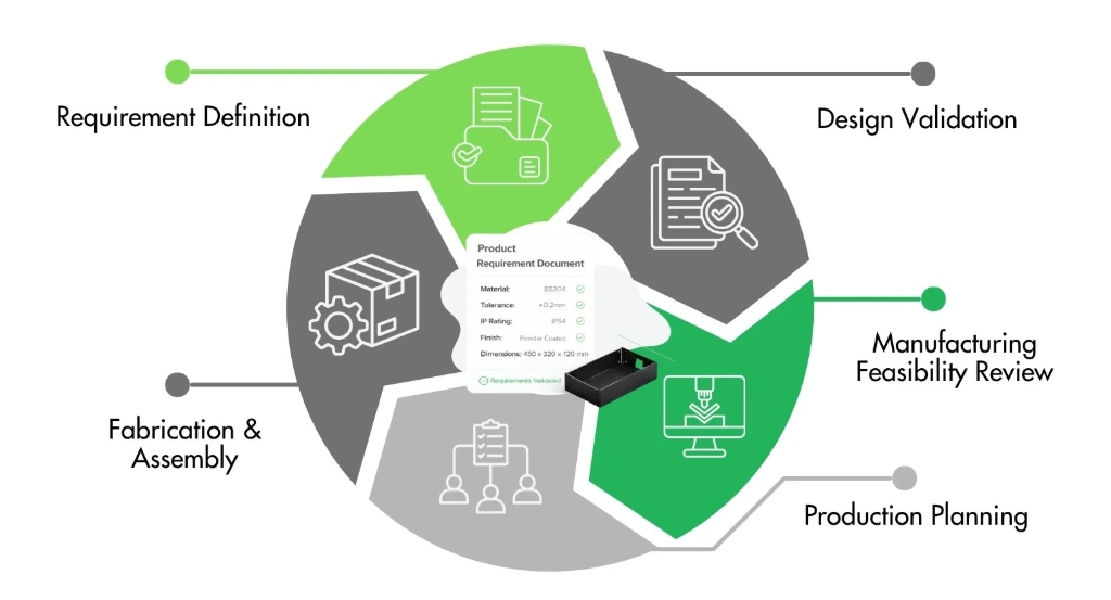
Across services such as sheet metal fabrication, CNC machining, 3D printing, and injection molding, this structured requirement review helps teams move from design to manufacturing with greater predictability.
If your project involves customized enclosures or custom mechanical parts, you can also explore how customization decisions influence manufacturing performance in our detailed blog.
Contact us and our team can help review your requirements and identify suitable production approaches.
FAQS
Frequently Asked Questions
A PRD is a structured document that defines functional requirements, dimensional limits, materials, and environmental conditions before production begins.
A PRD helps align design intent with manufacturing capability, reducing ambiguity and improving production predictability.
A PRD includes functional objectives, dimensional tolerances, material specifications, surface finishes, environmental conditions, and compliance requirements.
By defining measurable engineering parameters early, a PRD minimizes interpretation during fabrication and improves assembly consistency.
A PRD should be created early in development, before design validation and manufacturing planning begin.